Introduction: The Economic Case for Re-cabling
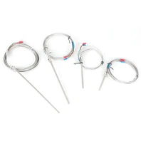
Long-probe thermocouples are essential components in industrial thermal systems, serving critical temperature monitoring functions in applications ranging from high-temperature furnaces and chemical reactors to industrial ovens and process heating equipment. These systems often operate under demanding conditions, exposing thermocouple cables to extreme temperatures, mechanical stress, chemical exposure, and environmental degradation. When cable failure occurs, many facilities default to complete thermocouple assembly replacement-a costly approach that overlooks a more economical alternative: re-cabling.
Re-cabling, the process of replacing only the extension wire while retaining the functional thermocouple probe and connection hardware, can reduce repair costs by 40-60% while maintaining system performance. This cost advantage is particularly significant for long-probe configurations, where the cable length (and thus material cost) constitutes a substantial portion of the total assembly expense. Beyond immediate cost savings, re-cabling extends the service life of existing probes, reduces equipment downtime, and minimizes waste-making it both an economically and environmentally sustainable maintenance strategy.
However, successful re-cabling requires more than simply swapping wires. It demands careful attention to wire selection, installation techniques, calibration procedures, and system integration. This guide provides a comprehensive framework for implementing re-cabling as a reliable maintenance solution, addressing both technical requirements and practical implementation considerations.
Understanding Thermocouple Fundamentals and Cable Function
To appreciate why re-cabling requires precision, it's essential to understand how thermocouples operate and the critical role extension wires play in temperature measurement accuracy.
- Thermocouple Operating Principle: Thermocouples generate a small voltage (typically microvolts per degree Celsius) based on the Seebeck effect-the phenomenon where two dissimilar metals joined at one end produce an electrical potential proportional to the temperature difference between the junction (hot end) and the reference point (cold end). This voltage signal must be transmitted accurately to the control unit for temperature calculation.
- Extension Wire Function: Unlike standard electrical wiring, thermocouple extension wires are not simple conductors. They must precisely match the thermoelectric properties of the thermocouple metals to avoid introducing measurement errors. For example, a K-type thermocouple (chromel-alumel) requires K-type extension wire with matching alloy composition. Using mismatched wire types-even if they appear similar-creates additional thermoelectric junctions that generate erroneous voltages, leading to temperature reading inaccuracies that can exceed 10°C or more.
- Signal Integrity Requirements: The extension wire must maintain signal integrity throughout its length. Factors such as wire insulation quality, conductor purity, connection integrity, and environmental protection all influence measurement accuracy. Even minor damage to conductors, oxidation at connection points, or electromagnetic interference can compromise the microvolt-level signals thermocouples produce.
When Re-cabling is Appropriate: Assessment Criteria
Re-cabling is not universally applicable to all thermocouple failures. Proper assessment of the existing assembly determines whether re-cabling is feasible or if full replacement is necessary.
- Suitable Conditions for Re-cabling:
- Cable-Specific Damage: When the extension wire shows visible degradation-insulation cracking, conductor corrosion, or physical damage-but the thermocouple probe itself remains intact and functional.
- Probe Integrity: The thermocouple probe (including the measuring junction and sheath) must be structurally sound, with no bending, cracking, or severe corrosion at the sensing end.
- Connection Hardware: Terminal blocks, connectors, and junction boxes should be reusable without significant wear or damage.
- Environmental Protection: The probe sheath must provide adequate protection against the operating environment; if compromised, re-cabling alone may not restore system reliability.
- Contraindications for Re-cabling:
- Probe Damage: If the measuring junction is bent, cracked, or corroded, re-cabling cannot restore measurement accuracy.
- Sheath Compromise: A damaged sheath that no longer protects the thermocouple element from the environment requires full replacement.
- Multiple Failure Points: When both cable and probe show significant degradation, complete replacement is typically more cost-effective.
- Specialized Configurations: Some thermocouple assemblies with integrated connectors or proprietary designs may not support field re-cabling.
- Assessment Protocol: Before proceeding, conduct a visual inspection of the entire assembly, measure insulation resistance, and perform a basic continuity test. If the probe shows stable resistance characteristics and the only issue is cable degradation, re-cabling is likely appropriate.
Step 1: Selecting the Correct Extension Wire
Wire selection is the foundation of successful re-cabling. The wrong choice can negate any cost savings through inaccurate measurements and premature failure.
- Matching Thermocouple Type: Extension wire must precisely match the thermocouple type (J, K, T, E, N, R, S, B, etc.). Each type has specific alloy compositions that produce characteristic voltage-temperature relationships. Using general-purpose wire or mismatched thermocouple wire introduces measurement errors. Always verify the thermocouple type (usually marked on the probe or connector) before purchasing replacement wire.
- Insulation Material Selection: Insulation must withstand the operating environment. Common options include:
- PVC Insulation: Suitable for temperatures up to 105°C; cost-effective for general-purpose applications but degrades rapidly above this temperature.
- Fiberglass Insulation: Rated for temperatures up to 500°C; provides good chemical resistance and mechanical durability.
- Ceramic Fiber Insulation: For extreme temperatures exceeding 1000°C; used in furnace applications but more fragile and expensive.
- Teflon (PTFE/PFA): Excellent chemical resistance and temperature rating up to 260°C; suitable for corrosive environments.
- Wire Gauge and Length: Use the same gauge as the original wire to maintain signal integrity. For long runs, consider using a slightly larger gauge to reduce resistance and voltage drop. Ensure the replacement length matches or slightly exceeds the original to avoid tension or stress on connections.
- Quality Considerations: Purchase wire from reputable suppliers that provide calibration certificates or traceability documentation. Lower-quality wire may have inconsistent alloy composition or insulation properties, leading to measurement drift over time.
Step 2: Installation Best Practices and Connection Techniques
Proper installation ensures long-term reliability and measurement accuracy. Rushed or improper techniques can create new failure points.
- Wire Routing and Protection:
Route extension wires away from high-voltage cables, motors, and other sources of electromagnetic interference (EMI) to prevent signal noise.
Avoid running wires parallel to power cables; cross them at 90-degree angles if necessary.
Use conduit, cable trays, or protective sleeving in areas with mechanical abrasion, chemical exposure, or high temperatures.
Maintain adequate slack to prevent tension on connections, especially in areas with thermal expansion or vibration.
- Connection Preparation:
Strip wire insulation carefully using proper stripping tools-avoid nicking or damaging the conductors, as even minor damage can affect signal transmission.
Clean conductor ends with isopropyl alcohol or contact cleaner to remove oxidation and contaminants.
For stranded wire, twist strands neatly and apply a small amount of anti-oxidant paste (especially for base metal thermocouples like J and K types) to prevent oxidation at connection points.
- Termination Techniques:
Use appropriate terminal blocks or connectors designed for thermocouple applications-standard electrical terminals may not provide adequate contact or temperature stability.
Ensure connections are tight and secure but avoid over-tightening, which can damage conductors or terminals.
For high-temperature applications, use ceramic terminal blocks or high-temperature connectors that maintain insulation properties at elevated temperatures.
Label both ends of the extension wire with thermocouple type and polarity to prevent connection errors during future maintenance.
Step 3: Post-Installation Calibration and Verification
Calibration is essential after re-cabling to ensure measurement accuracy. Even with perfect installation, small variations in connections can affect the thermoelectric output.
Calibration Methods:
- Comparative Calibration: Compare the re-cabled thermocouple against a known reference standard (such as a calibrated thermometer or another verified thermocouple) at a stable temperature point. This can be done using a temperature bath, dry block calibrator, or even a stable ambient temperature environment.
- Portable Calibrators: Use handheld thermocouple calibrators that can simulate or measure thermocouple signals. These devices are cost-effective and suitable for field calibration.
- System Calibration: If the control system allows, perform a system-level calibration by adjusting the input offset or scaling factor in the temperature controller.
- Verification Points:
- Check at multiple temperature points if possible, especially near the operating range of the application.
- Verify both the cold junction compensation (if applicable) and the overall measurement accuracy.
- Document calibration results, including date, reference standard used, and any adjustments made.
- Acceptance Criteria: The re-cabled thermocouple should read within the manufacturer's specified accuracy for that thermocouple type. For industrial applications, ±1-2°C accuracy is typically acceptable; for precision applications, tighter tolerances may be required.
Step 4: System Integration and Environmental Protection
After successful re-cabling and calibration, proper system integration ensures long-term reliability.
- Environmental Sealing:
Use appropriate sealing methods at connection points to prevent moisture ingress, especially in humid or outdoor environments.
For high-temperature applications, use high-temperature sealants or ceramic putty to protect connections.
Ensure junction boxes or connection enclosures are properly sealed and rated for the operating environment.
- Strain Relief:
Install strain relief devices (cable glands, clamps, or loops) near connection points to prevent mechanical stress on terminations.
In areas with vibration, use flexible conduit or vibration-dampening mounts.
- Documentation and Labeling:
Update maintenance records to document the re-cabling procedure, including wire type used, installation date, and calibration results.
Label the thermocouple assembly with re-cabling information for future reference.
8. Common Pitfalls and How to Avoid Them
Pitfall 1: Mismatched Wire Types
Symptom: Consistent temperature offset or erratic readings.
Prevention: Always verify thermocouple type before purchasing wire; use color-coded wire or labeling to prevent confusion.
Pitfall 2: Inadequate Insulation
Symptom: Premature insulation failure, short circuits, or measurement drift.
Prevention: Select insulation material rated for the maximum operating temperature plus a safety margin; consider environmental factors like chemical exposure.
Pitfall 3: Poor Connections
Symptom: Intermittent readings, signal noise, or open circuits.
Prevention: Use proper termination techniques, clean connections, apply anti-oxidant paste, and ensure secure mechanical connections.
Pitfall 4: Skipping Calibration
Symptom: Inaccurate temperature readings that may go undetected.
Prevention: Always perform post-installation calibration; document results and establish a calibration schedule.
Pitfall 5: Ignoring Environmental Protection
Symptom: Corrosion, moisture ingress, or mechanical damage over time.
Prevention: Use appropriate sealing, conduit, and protective measures based on the operating environment.
Economic Analysis: Cost Savings vs. Full Replacement
Cost Components:
- Full Replacement: Includes cost of new thermocouple probe, extension wire, connectors, labor for removal and installation, and system downtime.
- Re-cabling: Includes cost of extension wire only, labor for re-cabling, calibration time, and minimal downtime.
- Savings Calculation:
For long-probe thermocouples (typically 1-10 meters), the cable cost can represent 30-70% of the total assembly cost. Re-cabling eliminates the probe cost, resulting in savings of 40-60% compared to full replacement. Additional savings come from reduced downtime (re-cabling is typically faster than full replacement) and extended probe lifespan.
- Return on Investment (ROI):
For facilities with multiple thermocouples, implementing a re-cabling program can yield significant annual savings. The payback period for training and tool investment is typically less than one year for medium to large facilities.
- Non-Monetary Benefits:
- Reduced equipment waste and environmental impact
- Extended asset utilization
- Improved maintenance flexibility
- Enhanced troubleshooting capabilities through better understanding of thermocouple systems
Conclusion: Implementing a Sustainable Maintenance Approach
Re-cabling thermocouple assemblies represents a practical, cost-effective maintenance strategy for long-probe configurations where cable degradation is the primary failure mode.
By following a systematic approach-proper assessment, correct wire selection, meticulous installation, thorough calibration, and adequate protection-facilities can achieve reliable temperature measurement while significantly reducing maintenance costs.
The key to success lies in treating re-cabling not as a simple wire replacement task, but as a precision maintenance procedure that requires technical knowledge, proper tools, and attention to detail. For complex systems, specialized thermocouple types, or critical applications, professional assessment and service may be warranted to ensure optimal results.
Ultimately, re-cabling should be integrated into a comprehensive thermocouple maintenance program that includes regular inspection, preventive maintenance, and performance monitoring.
By adopting this approach, industrial operations can extend equipment life, reduce operational costs, and maintain process reliability in temperature-critical applications.

One-stop Thermocouple Factory in China
Jaye Heater Technology specializes in industrial heating elements, offering OEM/ODM services for global clients.